- Home
- Technical Resources
- Application Notes
- APX-065
Alternating Pulse Lights
 Click to Zoom
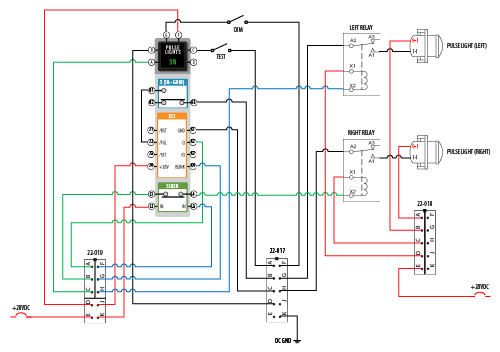
Often, design applications require activation and sequencing of high current devices such as lighting systems, solenoids or actuators. Depending on the design, these systems can have various activation triggers and specific repetitive timing requirements. This type design function can be easily accomplished with standard NEXSYS Components. This example activates a high intensity pulse light system which is activated by pressing a switch and each light alternates on/off at a frequency of 1 Hz from left to right. Both lights are never on at the same time and when the switch is pressed again, the lights are off. The function is accomplished with a momentary action switch containing a single switch pole an Electronic Latch (EL1), a Normally Closed Solid State Relay (SSR2H) external terminal blocks and external mechanical relays.
Application Truth Statements:
- Upon power-up EL1 outputs are High-Z (Open), Normally- Closed (NC) SSR2H is conducting, and the “ON” indicator is NOT energized, Pulse Lights are NOT energized.
- Pressing the momentary switch triggers EL1 /TGL input which toggles Q to Active Low (Ground), and BLINK to oscillate High-Z (Open)/Low (Ground) at the frequency of 1 Hz.
- EL1 Active Q output (K2).
- Active Q provides Low (Ground) to SSR2H (NC) switch contact.
- Active Q Active Q provides Low (Ground) energize the “ON” indicator.
- EL1 Active BLINK output (K4).
- When Low (Ground), Active BLINK, controls the Left Pulse Light (ON/OFF) at the frequency of 1 Hz.
- When High-Z (Open), Active BLINK, controls the Right Pulse Light (ON/OFF) at the frequency of 1 Hz.
- Alternating Pulse Light (1 Hz) functionality.
- When EL1 Active BLINK is High-Z (Open), the Normally Closed (NC) SSR2H conducts, switching the EL1 Q Low (Ground) – the Right Pulse Light is alternating (ON/OFF) at the frequency of 1 Hz.
- When EL1 Active BLINK is Low (Ground), the Normally Closed (NC) SSR2H is NOT conducting, and the EL1 Q Low (Ground) is removed – the Left Pulse Light is alternating (ON/OFF) at the frequency of 1 Hz.
- Pressing the momentary switch returns the circuit to power-up condition.
- Diode isolation is recommended to prevent a sneak path to the control circuit from the “ON” indicator and relay coils.
- Output Load capacity the EL1 outputs is 2.0 A (Resistive) and the SSR2H is 250 mA (Reistive).
Disclaimer: The configurations and diagrams shown above are provided by Applied Avionics, Inc. as a general example only. The recipient is solely responsible for actual design, electrical wiring, validation, testing, applicability and functionality of the product in regards to the customer’s specific application.
