The NEXSYS Solid-State Relay (SSR) includes Series A (4 pin) and Series C (8 pin) components that afford custom digital and analog signal control, as well as audio and data switching. The SSR performs similar functions of a standalone mechanical relay without the challenges of external packaging. The broad operating voltage range affords its use in numerous applications from simple polarity reversal to logic gate functions including AND, OR, and BUFFER.
Solid State Relays are activated by applying a DC voltage across the inputs. The SSR control bridge is bi-directional, which allows DC voltages to be applied in either direction for polarity insensitive design flexibility. There are three nominal voltage input options for the Series A (Single SSR) device and one input voltage for the Series C (Combination SSR) device, as described below.
NEXSYS Solid-State Relay outputs refer to the solid-state switch, which is available as Normally Open (NO) and Normally Closed (NC). The output load capacity of the NO option is 0.75 A (Resistive), and the NC option is 0.25 A (Resistive).
The number of outputs specified per unit varies as described below.
Series A (4 pin) single SSRs are available in Normally Open (SSR1) and Normally Closed (SSR2) versions. Both SSR1 and SSR2 have three nominal input voltage options; Low (+5 VDC), Med (+14 VDC), and High (+28 VDC). The current draw of the three voltage options are 12.1 mA (+5 VDC), 6.2 mA (+14 VDC), and 6.3 mA (+28 VDC). SSR3H is Normally-Open (NO). High (H) 28V (Nom.), 10 mA (Nom.), 8V (Min.), 7 mA (Nom.).

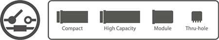
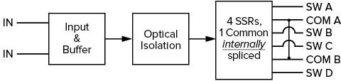
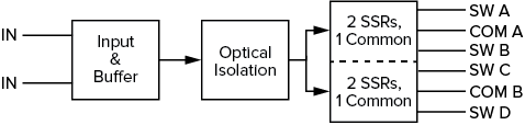
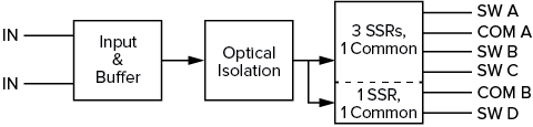
Series C (8 pin) combination SSRs allow for four individual switches (SW) to be synchronized in three different combinations (described below) when +28 VDC is applied across the inputs. For each of the combinations, the switches can be specified to be Normally Open (NO) or Normally Closed (NC). The current draw is 25.2 mA (+28 VDC). As a Series C device, Combination SSRs cannot be packaged in a VIVISUN Compact body.
Four Switch Single Common: Four (4) SPST contacts (or switches) with a single internally spliced common.
Dual Switch Pair: Four (4) SPST contacts (or switches) in two pairs connected with one common per pair.
Three Switch Single Common, One Switch Single Common: Three (3) SPST contacts (or switches) connected to one common and one (1) SPST contacts (or switches) connected to another common.
To help system designers understand the potential of NEXSYS Component Technology, we have assembled a collection of Application Notes. The links below show example applications that utilize the Solid State Relay component.
Cabin Call with Signal Invert
 This application diagram depicts an aircraft internal communication system (ICS) cabin call switch that can initiate a call and indicate system state. The switch can take external input signals of different voltage levels and invert them to provide active system state indication.
Audio Switching
 This application diagram depicts an indicator that selects and indicates the active audio source as determined by the position of the built-in alternate action switches. The switches control external relays which allow signals of the selected audio source to be sent to downstream systems.