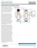
This application diagram details an oxygen valve control system. The design converts momentary switch presses into timed pulses to actuate the valve open and closed. Once the valve is opened, positive indication of oxygen flow is provided via a flow sensor internal to the valve. As an added feature, the system always defaults the valve to the closed position on power up to prevent any potential issues.
In its relaxed state, the “STBY” legend of the LED indicator is illuminated since the SPDT-DB switch is providing a path to ground through the normally-closed (NC) position of the switch contact.
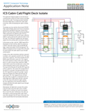
This application diagram details an aircraft internal communication system (ICS) that connects the flight deck with the cabin. The design provides flexibility that allows flight deck to isolate from cabin audio at any time, while still allowing the cabin to initiate a call.
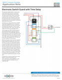
This application diagram depicts a mission power system switch with an electronic switch guard instead of the traditional physical switch guard. The mission power switch contacts must be held closed for at least 3 seconds to activate and de-activate the power relay. Inadvertent contact with the switch for less than 3 seconds will be ignored preventing power from being applied accidentally to downstream mission busses.
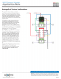
This application diagram depicts an autopilot system status annunciator with a built-in multi-bit converter. The converter reads the ARINC 429 data and decodes the selected label and bits. Each bit has a dedicated output which when active, illuminate indicators that correspond to the active status of the autopilot system.